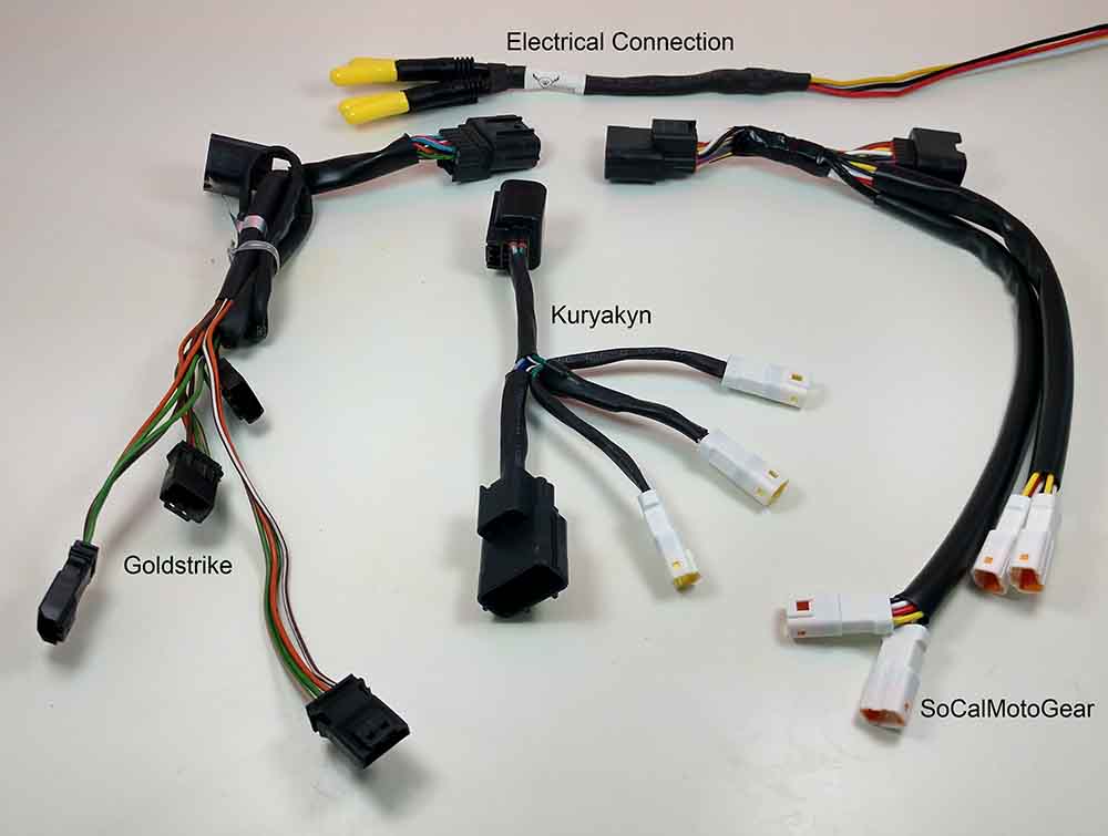
If you happen to be installing a product from an EC or a competitor that you will be wiring into an isolator or distribution block, here are the wire color codes that you will need to know. Info current as of 6/2/20
Electrical Connection
ground – black
tail – white
brake – yellow
signal – red
Goldstrike
ground – solid green
tail – brown
brake – green w/ red stripe (looks pink)
signal – orange (left) and blue (right)
Kuryakyn
ground – solid green
tail – brown w/white stripe
brake – green w/ red stripe
signal – orange (left) and blue (right)
SoCalMotoGear
ground – black
tail – white
brake – red
signal – orange (left) and blue (right)
CanBus is CanBus, right? Only on paper.
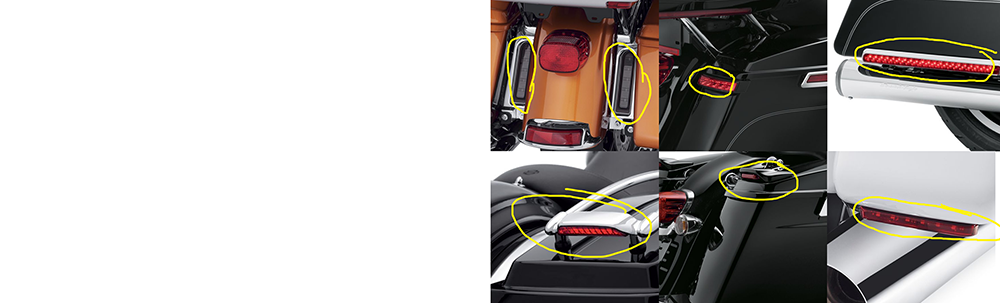
So what is the difference? We made this easy. In one picture.
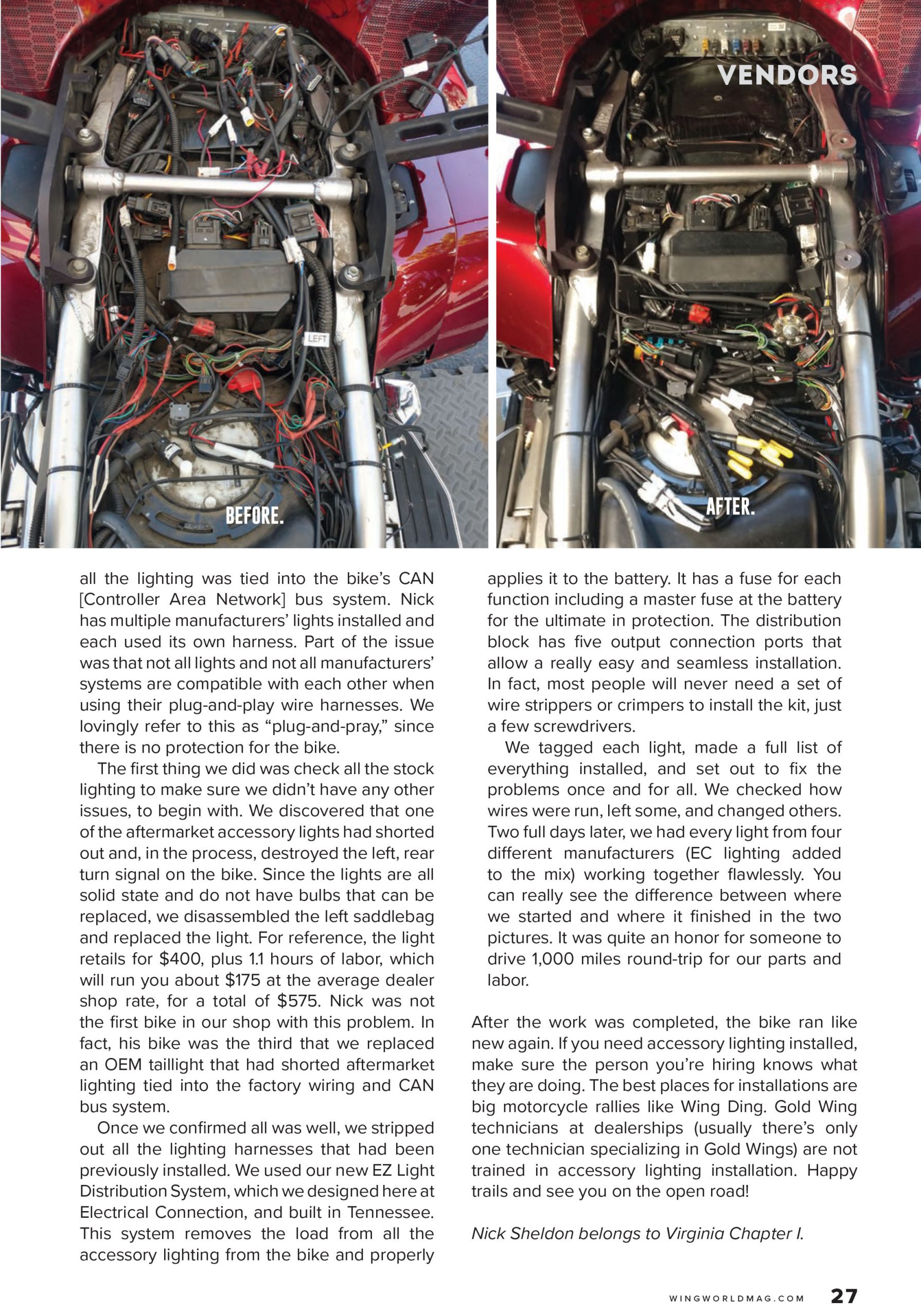
In the above pic, you see all the accessory lighting items that Honda offers for the 2018+ Goldwing circled in red. Now we have taken out anything that Honda added a specific circuit or connector for; 3rd brake light, puddle lights, and fog lights. By the way, you should see nothing circled in red and that is on purpose. Honda does not offer any lighting products.
The items circled in yellow in the pic shows all the accessory lighting items that Harley offers for the Ultras. All of these connect into the factory wiring for the rear lighting. They are NOT connecting into specific circuits. They all piggyback into the main harness.
Ok. So why should you care? This visual shows us that Honda did not create any extra allowance into the CanBus system to power extra lighting. Harley did. By designing lighting products that plugin as they do, Harley made sure that the rear lighting was robust enough to power all those extras. And has protection measures built into the BCM (body control module) that runs the lighting.
Plug & play safely, friends.
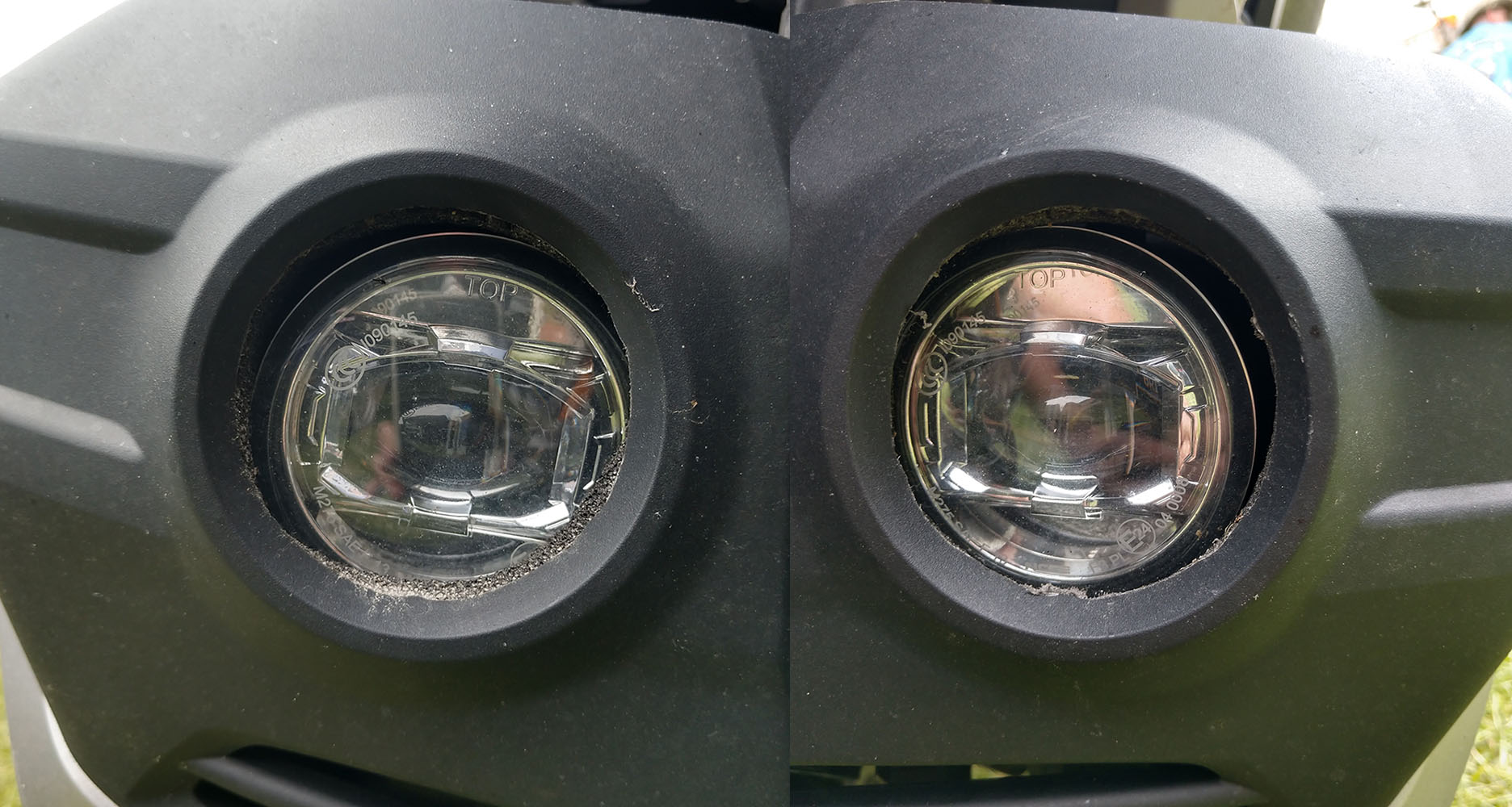
When the first kits started showing up on bikes, we noticed something. Many were like the first version of the OEM kits where the light was not aligning itself with the hole in the cowl. This ends up with you having light you paid for end up behind the cowl and never making its way on the road as intended. Plus, I’m OCD. We don’t just design products that work well – they have to look the part as well.
In the pic above, you can see the OEM Honda kit installed and how badly aligned they are. This is both sides on the same bike.
Electrical Connection is the only company to build lights that have adjustment. And now you know why.
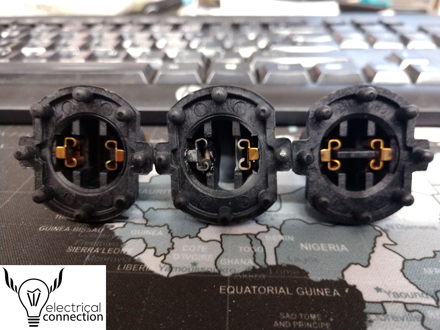
So we have discovered that Honda has updated the little adapter your H7 headlight bulb plugs into.
The one on the left in the picture is a brand new, unused old style. The one in the center is a burned up unit. Notice the discoloration of the left terminal. The customer was commenting that his bulb would work on occasion. This is actually a common occurrence for those that have not transitioned to LED.
The adapter on the right is the updated unit. Notice it has a brace going between the two terminals. This is to stop vibration. This vibration can cause the bulb to make short, intermittent contact. This break in contact causes the terminals to heat up and cause the damage as shown on the left adapter. The terminals themselves also appear to be thicker and more robust.
If you find yourself replacing your adapter, make sure it has the brace between the 2 terminals. This should greatly help with the longevity of your adapters.
So we had been holding off from releasing certain items for the new bike until we could review the ETM and schematics for the bike. After doing so, we have determined that Electrical Connection will not make items that plug and play into the factory wiring where the accessory will draw power from the factory wiring, except where Honda designed it in (fog lights/puddle lights). Here is why.
We like you as customers and don’t want to sell you something that could damage very expensive things on your bike. Aka, computers and CanBus.
So how many computers (modules) are on the 2018 Goldwing / Tour?
6 Speed – NINE; Smart Control module, Front module, Rear module, Combination Meter (Display), Audio/Nav module, Traction Control module, Engine Control module, Switch Panel, Reverse Control module and ABS module.
DCT – TEN; adds TCM module.
Airbag – ELEVEN; adds Airbag module.
While most CanBus systems eliminate fuses, the 2018 Goldwing still has some. Some. Not all. With that said, the power out from the fuse goes into the ‘controllers’ (module), and then out to the item or part. The module is a component in this chain. Why is this of relevance? Read on…
CanBus monitors each circuit. What and how it is done varies on the code that vehicles has. Currently, no one I’m aware of other than Mother Honda knows that code for the new Goldwing. But here is what most other CanBus systems monitor.
~too much current draw (too much power as in a short or overload)
~not enough current draw (a part is not working, therefore not using power)
~connected to the computer (the computer sends out current to a part to ensure it’s connected)
Let’s take a completely made up tail light circuit. The vehicle manufacturer says the light should draw a minimum of 0.75 amp and a maximum of 1.25 amps and normally a 1 amp load. If you add lights to the circuit that take the load over 1.25 amps, the computer monitoring the circuit would shut it off thinking there is a short because it’s over the load allowed. Normally some kind of indicator would show up on the dash to let you know about this, but it’s not going to say “hey you have added too many lights.” You might get something like “TAIL OUT” or “CHECK REAR LIGHT”.
A worse possible scenario. Your new light gets a pinched wire when it’s installed or there is a failure on the PC board where the LEDs are. This causes a short. You have now put the bike’s light circuit in this problem. More than likely, it should shut down the circuit in the computer module. Fix the problem, turn the key off and on and the computer will reset. Worst case you damage one of the modules on the bike. They only average $400. Plus all the labor that you will be out of pocket on as the tech will have to be good enough to find the problem as the bike’s diagnostic won’t tell him it’s the accessory and not the bike. And your warranty won’t cover this expense. Parts or labor.
We have decided that we are going to offer a complete separate system to power any and all of your added lighting products. For anyone with a trailer isolator, you simply add our Power Distribution Module. Connect your trailer to the module as well for tail light, brake light, and left/right signal. Don’t have an isolator? No problem. We will have a complete kit with everything you need for not a lot more money than what other companies sell just a harness for. The connections for triggers will be Plug & Play. If something in the mix has a short, it can not or will not affect your bike, it’s computers or your warranty.
We are doing this in your best interest. I ride. I own one of these things. I am not comfortable with just plugging into the factory wiring on my bike, so I won’t do it on yours. Hope this all makes sense.
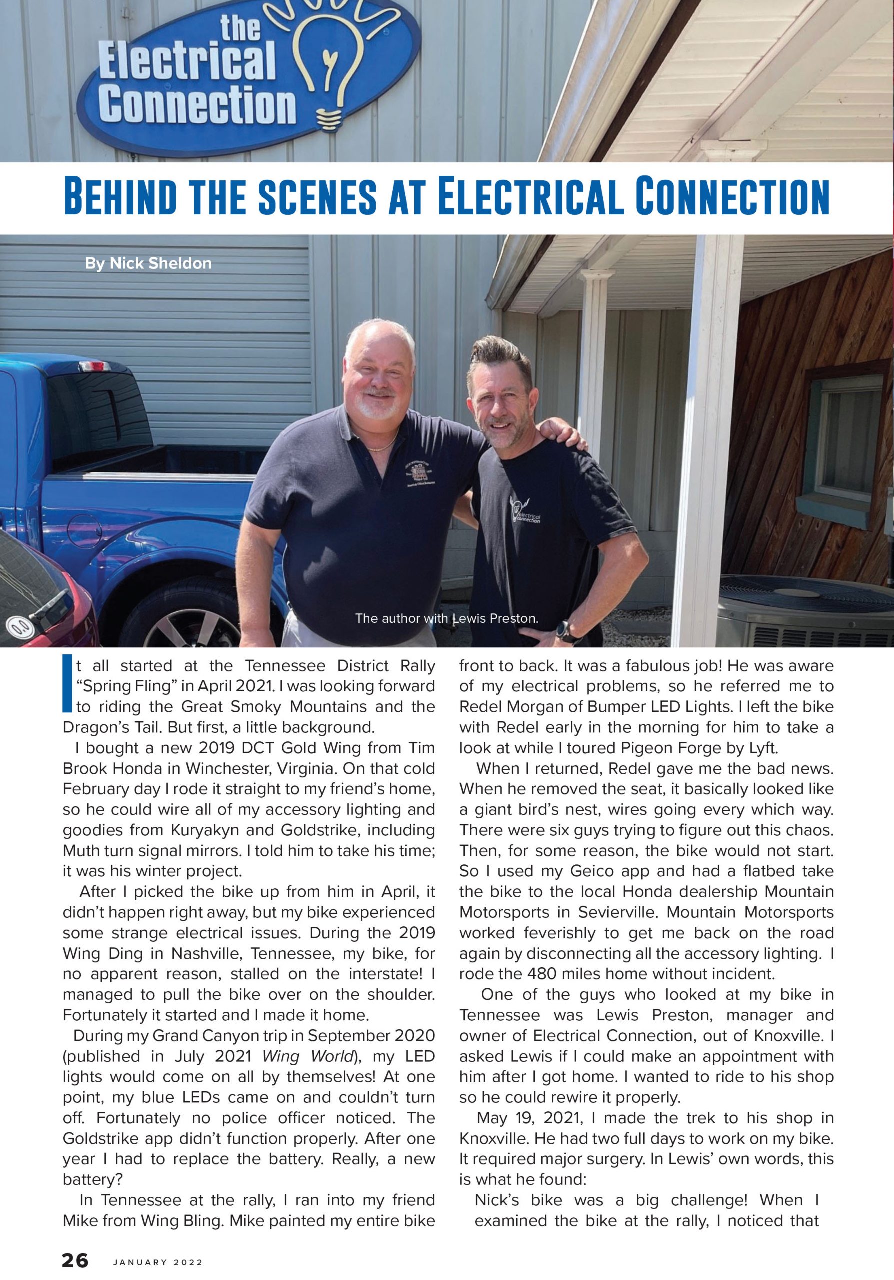
Lewis
So with the release of this bike, there has been a ton of questions about CanBus. What does it control? What does it not control?
What is CAN? CAN stands for Controller Area Network. CAN was designed in the 1980s because of limitations of existing serial buses for use in cars. You can dive in more about CAN history in this article: History of CAN technology
Honda is kinda late in the CAN game. BMW has been the powerhouse for years in the use of CAN. Indian uses it extensively and Harley started in 2011 on the Softails and 2014 on the Ultras.
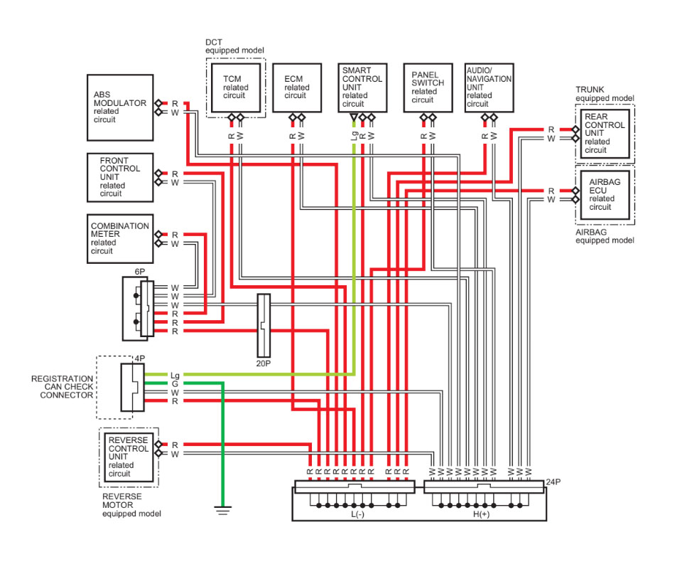
On the physical layer, CAN consists of two dedicated wires for communication. These wires are called CAN high (red wires in above picture) and CAN low (white wires). These 2 wires are connected to and create all the communication between all the CAN controlled Units on the motorcycle.
The main brain of this system is the “Smart Control Unit”, but other modules work in conjunction with it. These include the TCM (Traction Control Module), ECM (Engine Control Module), and the Front and Rear Control Units (among many others, but that will be our focus).
The Front Control Unit does more tasks than the rear. It takes data from CAN high and low and controls everything from the heated grips to the headlights. It also takes the inputs from the handlebar controls for various functions. The switches use varied amounts of resistance for each function so that the Control Module knows what function you are trying to control. The Rear Control Unit does the seat heat, suspension adjustments and some other, but mostly those 2. Most traditional CAN systems remove fuses and relays, but the new Goldwing does retain some. Our initial view of the Honda CAN system shows the Front & Rear Control Units are fully responsible for supplying power for some functions, but others have their own fuses. This does not mean you should tap into those circuits that do have fuses as the Control Units still have inputs from those wires; this means they are monitoring them at some level.
In a traditional CAN system without fuses, the CAN knows that a certain circuit will have a minimum and a maximum amount of current set in the threshold. Too much current draw and the CAN will think there is a short and shut off. Not enough and the CAN will think whatever it’s trying to operate isn’t working. Most cases either of these can cause the CAN to shut off as a method of protection and in some cases will display a fault code on the dash.
Ok…so I know what are you asking at this point. Can I just tap into the existing wires like we used to? Probably not. I’ve not been able to fully research all the ins and outs of this system. Especially with the circuits that have fuses. If you do tap into it, and you hit the wrong wire, or you were to apply more load than the computer wants to see, there is a chance the bike will shut off that circuit until you get the bike to Honda and have the CAN examined. And as of my writing, dealers do not yet have the tools to do so. This could lead to problems with warranty as CAN wires do not like to be disturbed.
Seems like every time I turn around, there is some new type of fuse. We are going to focus on the ones most commonly used in the powersports industry.
Maxi.
Used as the main fuse between the battery and the fuse box or large drain devices.
ATC.
Was the industry standard. Is losing favor to the ATC Mini.
ATC Mini.
Probably the most common type we encounter.
ATC Mini Low Profile.
One of the newer kids on the block.
Micro2 and Micro3.
The newest generation fuse. More common in automobiles.
Stay tuned for the next installment where we teach you what value fuses to use.
As any motorcycle ages, design defects begin to show. Things the manufacturer can’t simulate in a few years of testing.
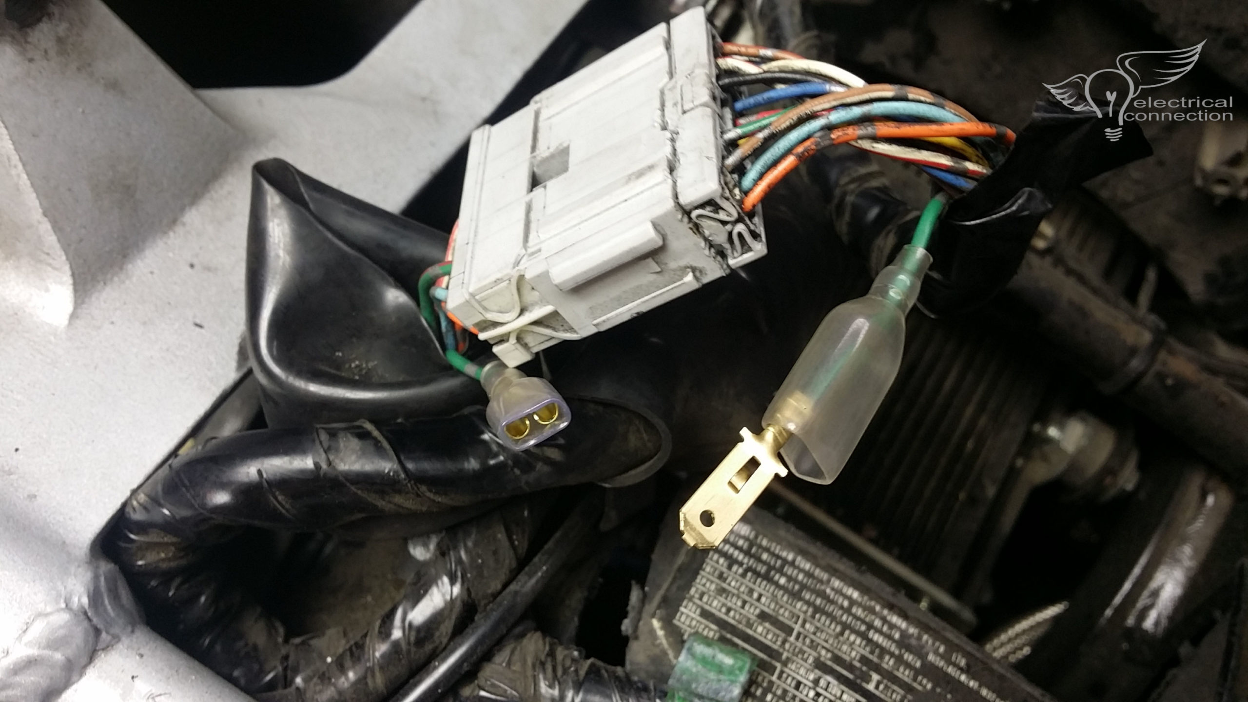
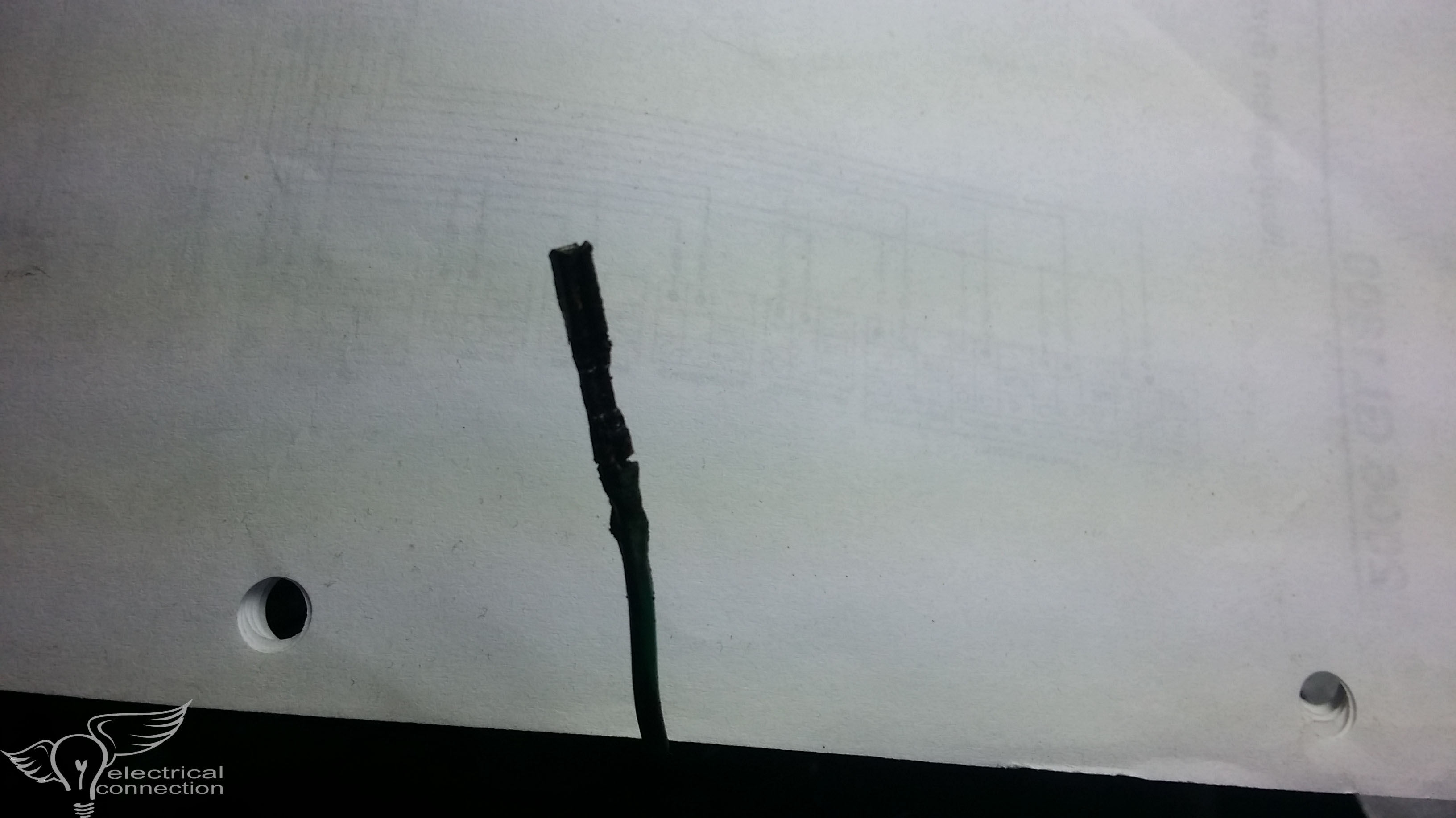
One of those are 2 ground wires on the GL1800. The first one is up behind the left fairing pocket. The one we are going to discuss is the rear light feed.
If your bike has strange light issues…turn a signal on and the other ‘ghost flashes’ (faint glow). Hit the brakes and your turn signals come on. You more than likely have a ground issue. The bike we are about to show you is a 2006 GL1800. This large grey connector is the rear light feed. All the wires are 18ga except the ground; it appears to be 14ga…maybe a 16. The wire is large enough for the load, but the tiny metal terminal inside it is not. It gets hot from the resistance. This in turn damages the housing. Take a look at the pics…..
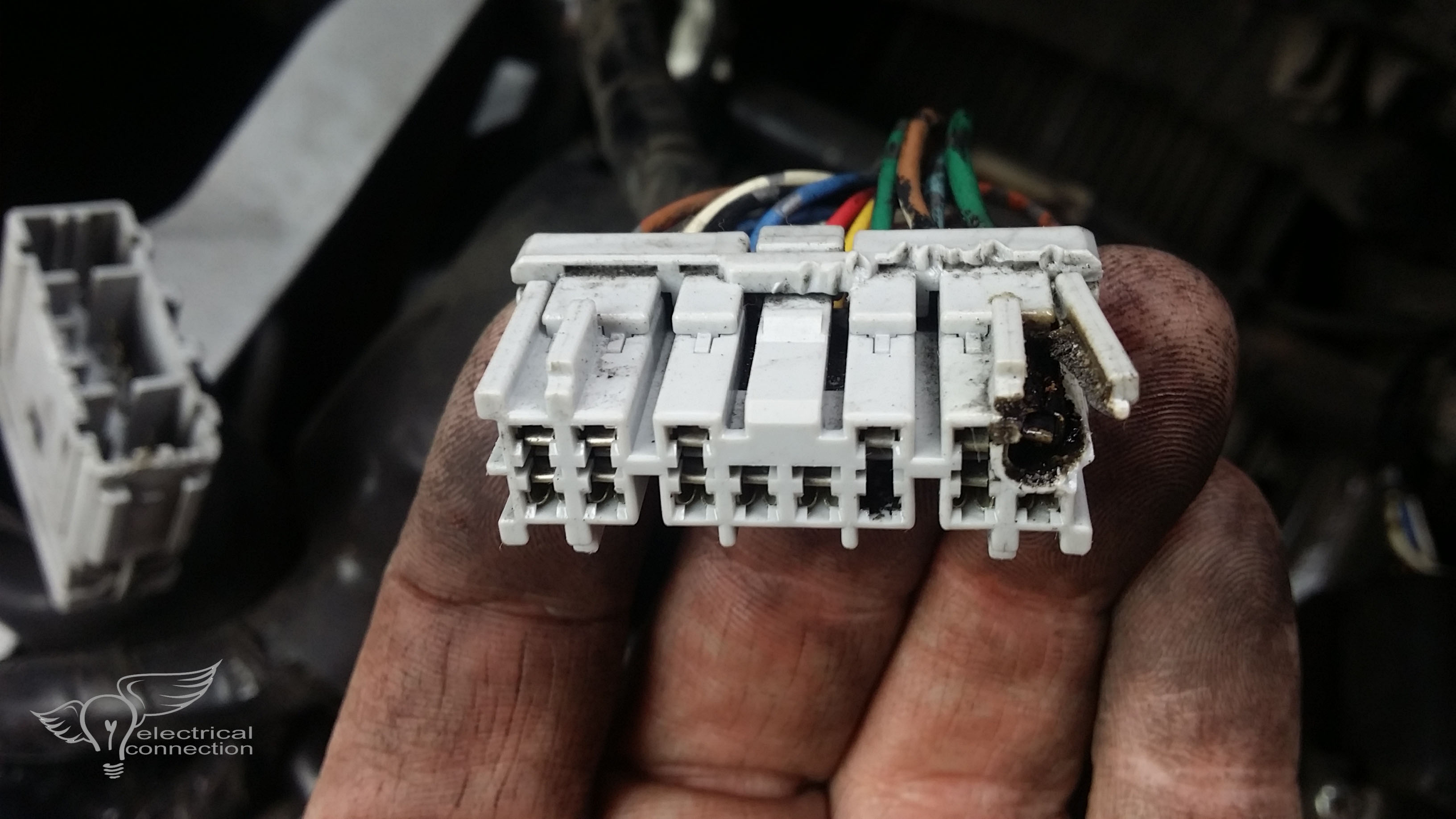
That is the ‘light side’ of the connector….those wires go to the rear tail lights. Below is the bike side.
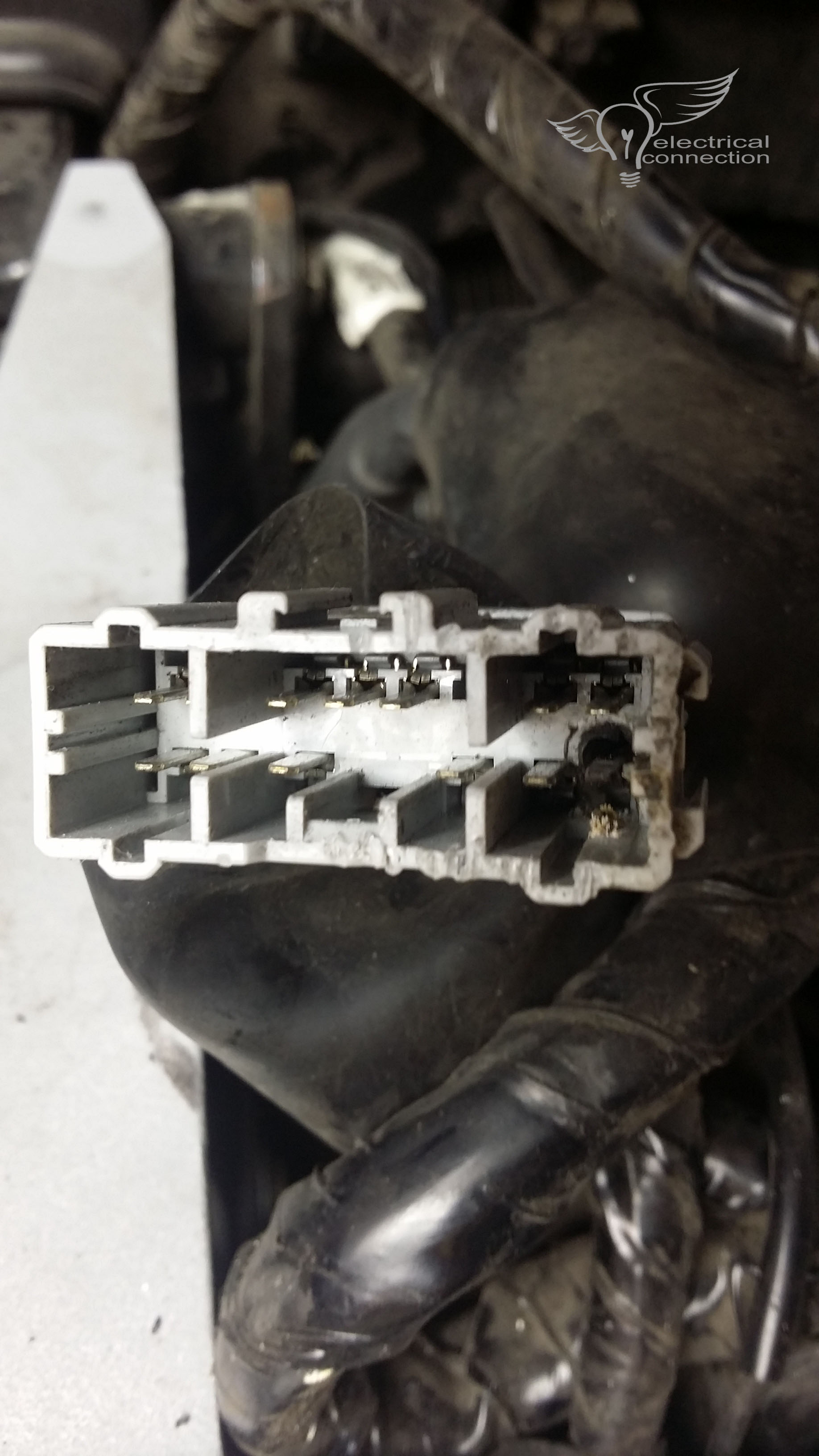
This is terminal that was removed from the plastic housing. Or what’s left of it. This was a brass terminal when it was built.
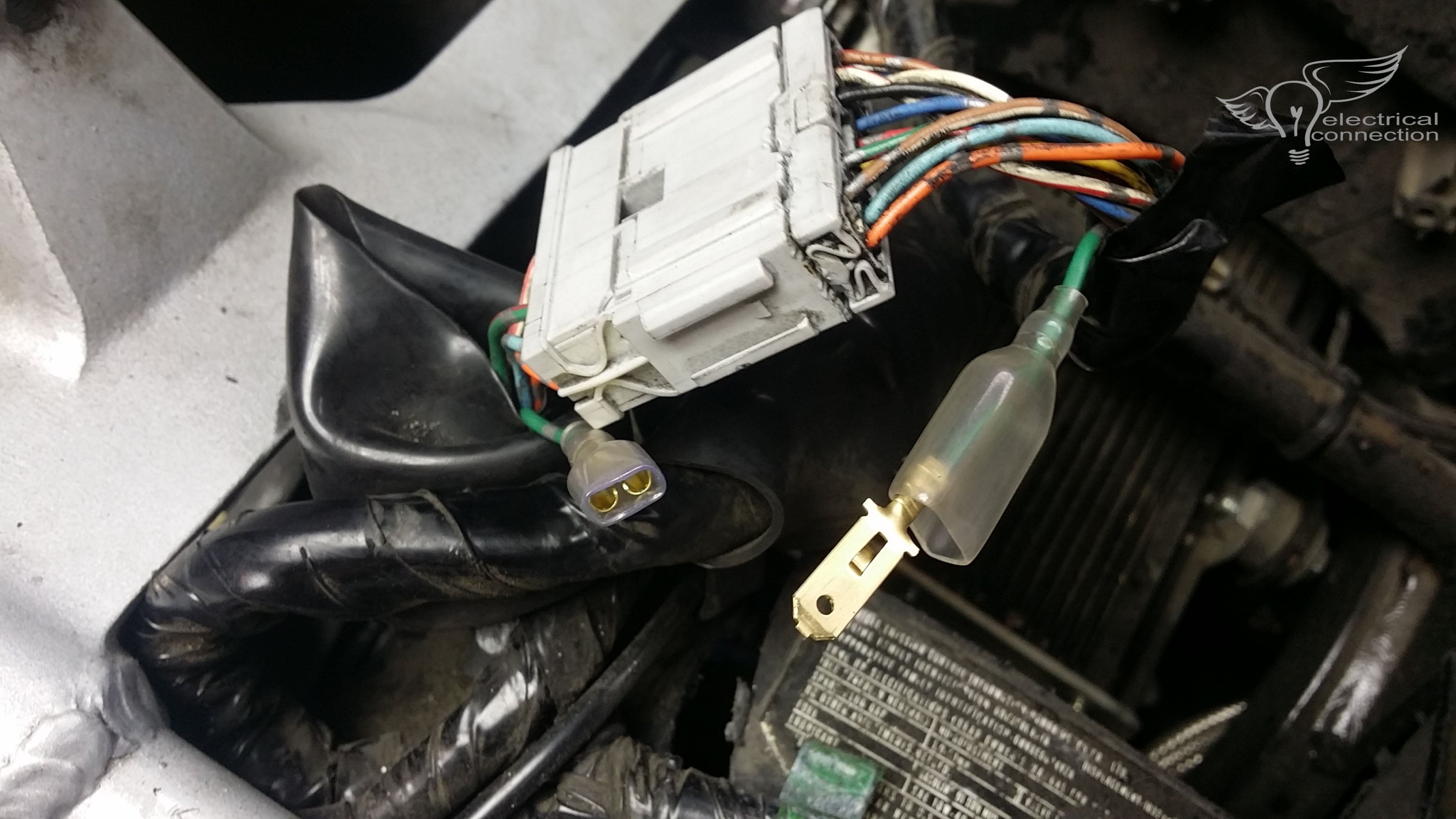
So what we did was remove that tiny terminal. We could not get the metal pin out of the other side due to heat damage. Cut the wire, stripped it back and installed a large brass terminal that was used on the GL1500 headlight. Way more surface area and reduced resistance make for an ideal fix.
DISCLAIMER.
Let’s get this out of the way, right meow.
This listing is a GUIDE.
If you don’t check before you connect, please list all your tools for sale on Craigslist.
Check it before you wreck it!
BMW
note – BMW is all over the map on tail and brake. Especially on single wire tail lights.
tail – gray w/black stripe OR blue w/gray stripe OR black w/gray stripe OR red/yellow/gray
brake – yellow w/gray stripe OR gray w/black stripe
left signal – blue w/red stripe
right signal – blue w/black stripe
high beam – white
low beam – yellow
ground – brown
CAN-AM SPYDER
tail – orange
brake – white
left signal – gray/pink
right signal – brown/yellow
ground – black
HARLEY DAVIDSON
tail – blue
brake – red w/yellow stripe
left signal – violet
right signal – brown
high beam – white
low beam – yellow w/black stripe
ground – black
HONDA
tail – brown w/ white stripe
brake – green w/red or yellow stripe
left signal – orange
right signal – light blue
high beam – blue
low beam – white
ground – solid green
KAWASAKI
tail – red
brake – blue
left signal – green
right signal – grey
high beam – red w/black stripe
low beam – red w/yellow stripe
ground – black w/yellow stripe
SUZUKI
tail – grey
brake – white w/black stripe
left signal – black
right signal – light green
high beam – yellow
low beam – black w/blue stripe
ground – black w/white stripe
YAMAHA
tail – blue
brake – yellow
left signal – brown
right signal – green
high beam – yellow
low beam – green
ground – black